|
Happy holidays everyone! Fist a quick apology, I’m sorry I haven’t posted for a bit. I’ve been swamped at work and with the holidays zooming in and all. I appreciate everyone who follows this board and I feel like I owe it to y’all to post a bit more regularly. So after the holidays i’ll be back to posting a bit more regularly, getting back to the Space Battleship Yamato project. Until then i’ve been painting miniatures for Warhammer 40,000, as a stop gap for more involved hobby-build time. So I’ll post up the pictures of those for you to enjoy. Here are my Primaris Space Marines Intercessor Squads. The Primaris Hellblasters Inceptor SquadPrimaris Lieutenants Apothecary Librarian Thank you again for following me and as always,
Keep Building!
0 Comments
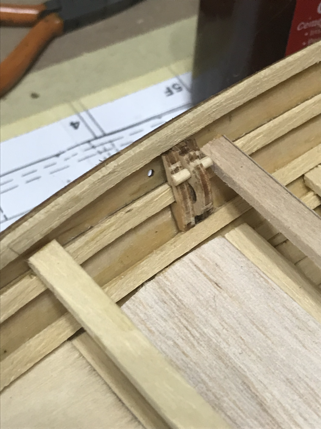
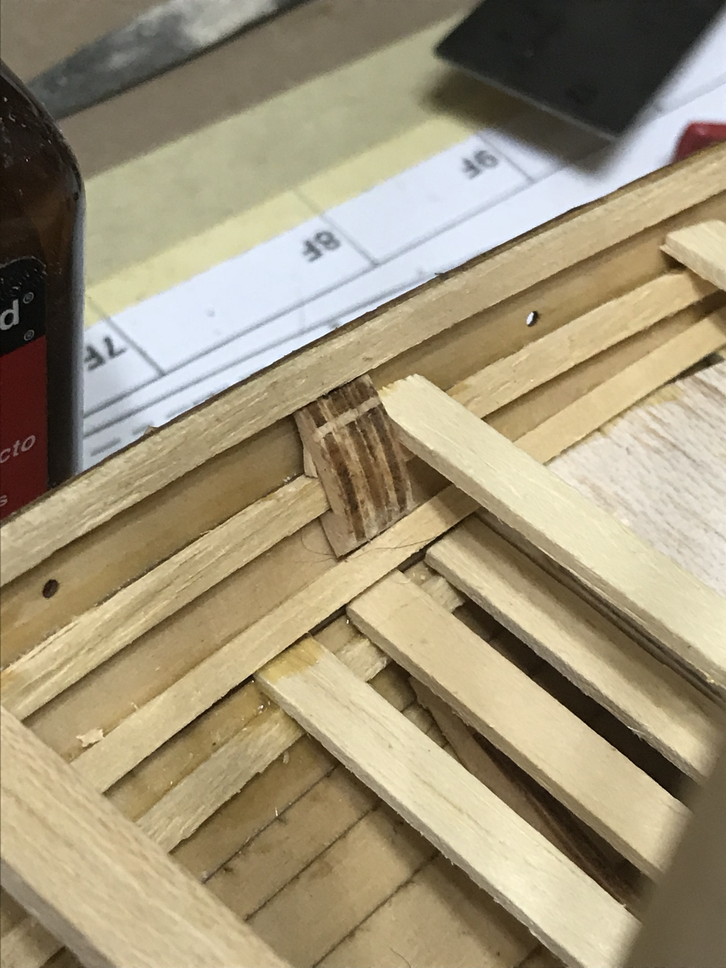
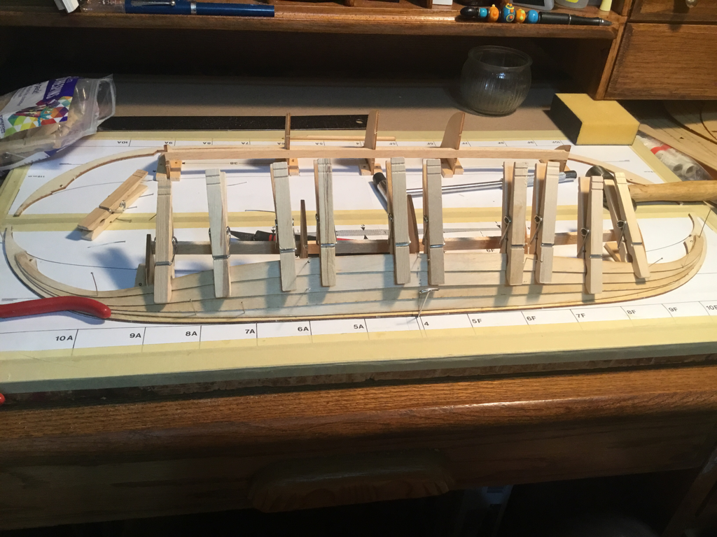
Sorry all things have been a bit hectic and my posting schedule has been a bit off. I’ll try and do better! Well hold tight this is gonna be along one!!! With the hull completed the next step is to add the rib supports. Each support must be sanded and fit individually to be snug to the strakes and the keel, and most importantly MUST be placed in their exact location careful measurements need to be made. The stern and bow plates are then glued and clamped into place. Next up we add the forward top plate .this tightens the bow strakes and lock them into place. The piece is glued, clamped and pinned into place to keep everything tight while the glue dries. While drying the gunnels are added to the inside of the hull, the cross beams and the benches will rest on these beams. These are cut and fitted to the curved hull, and clamed into place as the glue dries. Clamps are my friend! With the glue all dried and all the ribs, gunnels and plates in place the cross beams are added next, the care taken when placing the ribs pays off here as each cross-beam will fit onto the ribs and be the correct distance apart for the deck plating that comes next. 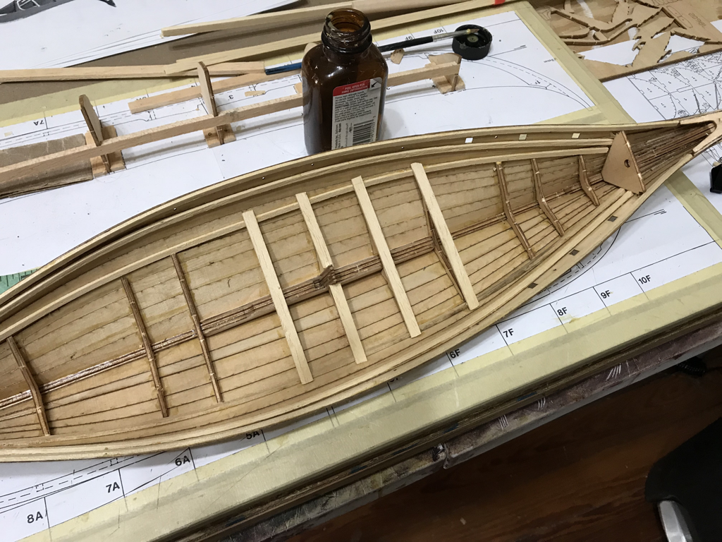 Once the cross beams are in place and while the glue is still tacky the deck plate are added, with the cross beams glue not fully set some minor adjustments can be make to make the crossbeams and the deck plate fit nice and tight. Now we set everything aside for the glue to cure. The crew benches come next, these benches rest on the next gunnel beam each needs to be sanded to fit the curve of the hull. The center mast support beam is mounted directly over the mast boot with a cutout for the mast to sit into. This cut out needs to be measured properly to keep the mast from leaning to the right or left. While the benches are drying the rigging cleats are assembled and put into place, along with the gunnel supports.
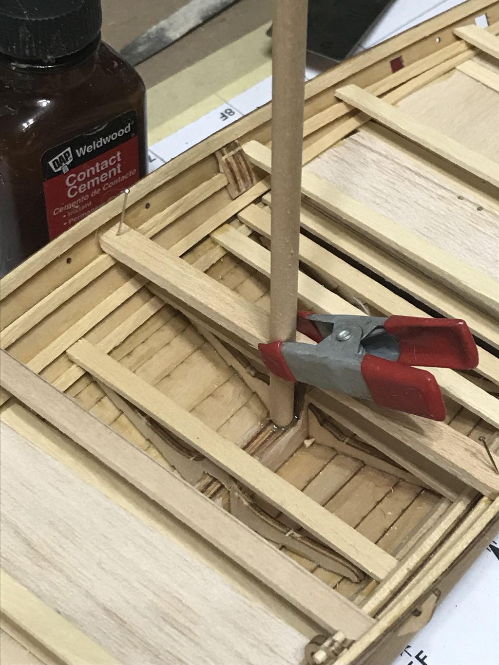
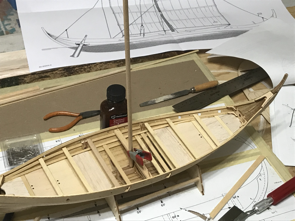
The mast is now seated into the mast boot and the cross support and clamped into place.
With all the clue curded, I added a coat of paint/stain to the hull and started all the rigging. The standing rigging is the primary support for the mast and keeps everything nice and tight. All the excess rope is coiled and glued into the forward and aft rope holds. The standing side rigging is in 2 parts for each side, the mainline running for the mast top to a pulley-lock and the support lines that are ties off to the hull and to one of the benches, this allows of the tension on the mast to be adjusted in rough weather.
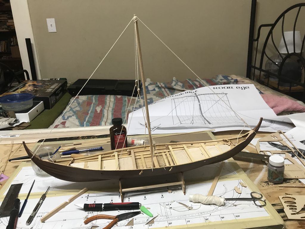
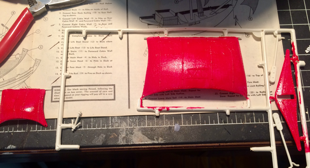
The canvas sail is given a running stitch around the top and bottom fold seam, and tied to the main boom. The boom is aligned to the mast and the mast and boom connect is tied into place. The mainsail line is attached to the boom and run through the mast and down to the jib pulley. The pulley lines are run from the left and right cleats and support through the hull, tases control the height of the boom and sail. The excess ropes are coiled onto the deck. Finely the sail tack lines ar attached to the sail corners and the boom ends and run through their cleats on the hull. With the final addition of the steer-board the Roar Ege is ready for her voyage. I hope you enjoyed this build. It was a lot of fun. Until next time, as always Keep Building!!
With the hull halves fully cured it was time to assemble the hull, using a liberal amount of contact cement the 2 keels were aligned and clamped together. The center board you see pinned is to make sure there is no warping of the hull while the cement cures, it will stay in place until the interior supports are added. 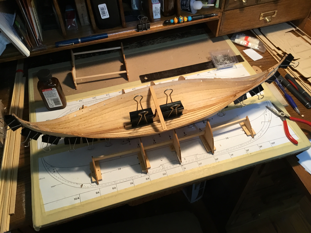 Once again the hull is set aside to allow the glue to cure for 48 hours, the next stems will be to make sure the hull strakes have no gapping, and the interior supports and the decking. So, as always, until next time, Keep Building!!
The Keel is laid. The interesting thing about building plank on plank kits is that there is a good deal of time spent building the support structure for building the ship itself! So here in these first two images you see the keel (in 2 halves) laid out with the mast support added, this had to be sanded round on one side to make room for the hull strakes. The uprights are the shaping supports for the hull strakes to lay against and will not be part of the completed hull. Here the first 2 strakes are laid onto the form. And pinned to the upright supports as the glue drys. The clothes pins keep the strakes together during the drying process. I’m using the suggested contact cement for my glue. This is fast drying but need time to cure totally. The glue is used by painting the area to be glued both the surface you are gluing to and the piece you are attaching, then you allow the contact cement to dry. The when the 2 glued surfaces come into contact they are nearly instantly bonded. Care must be taken to make sure you align your pieces correctly.
Good day all! Well the summer is ending, vacation is over and time to return to my model bench as the days slowly get shorter. We're going to have a change-up reall quick. I've been commissioned by a good friend to build a Viking Ship in honor of someone's passing. Needless to say I'll be putting the Yamato build on the back burner for a little bit whale I get cracking on this new build to finishe it up in time for the ceremony.
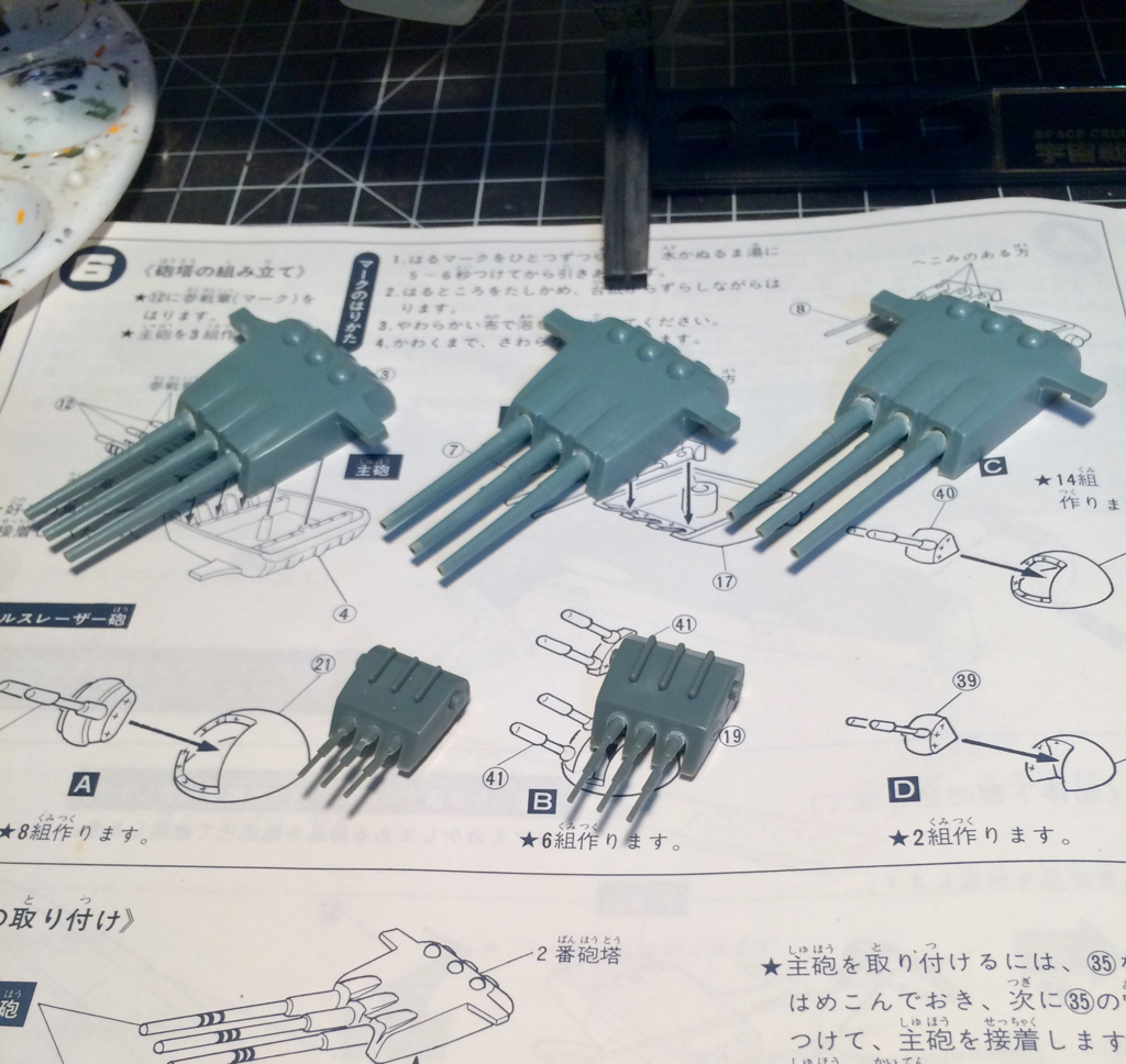
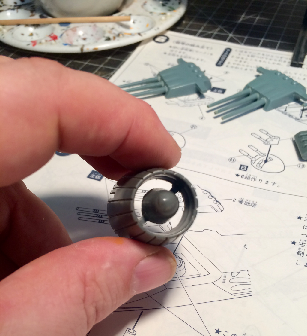
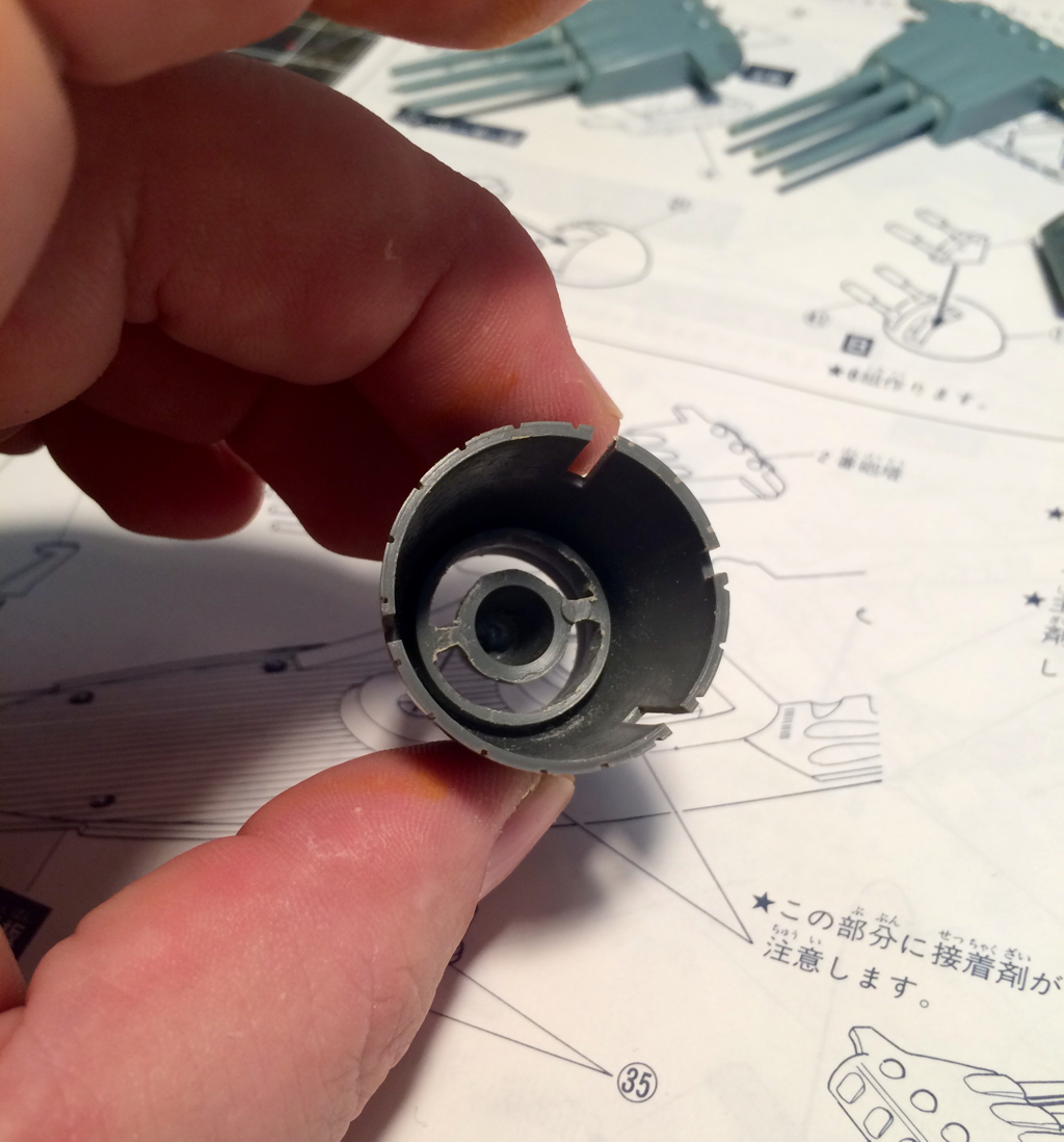
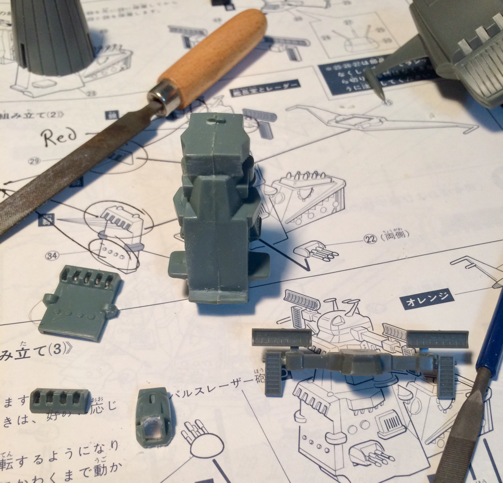
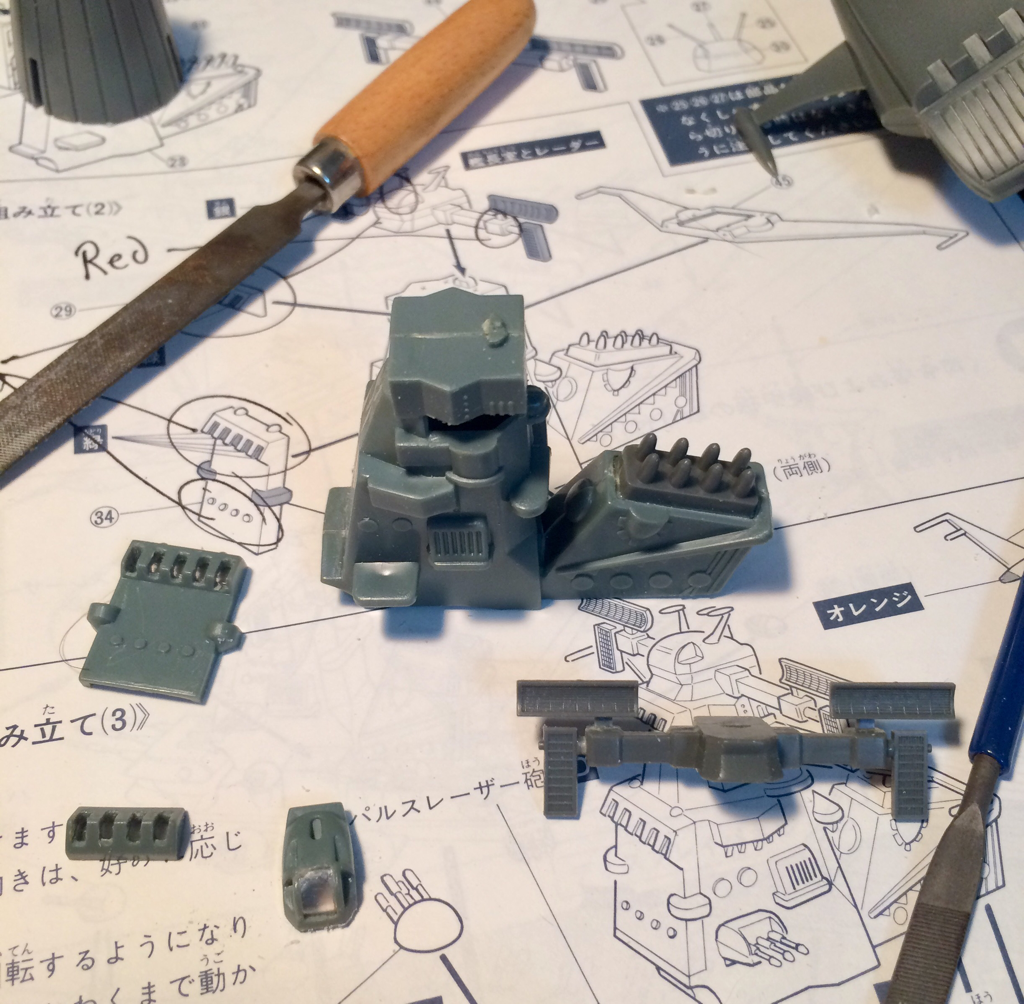
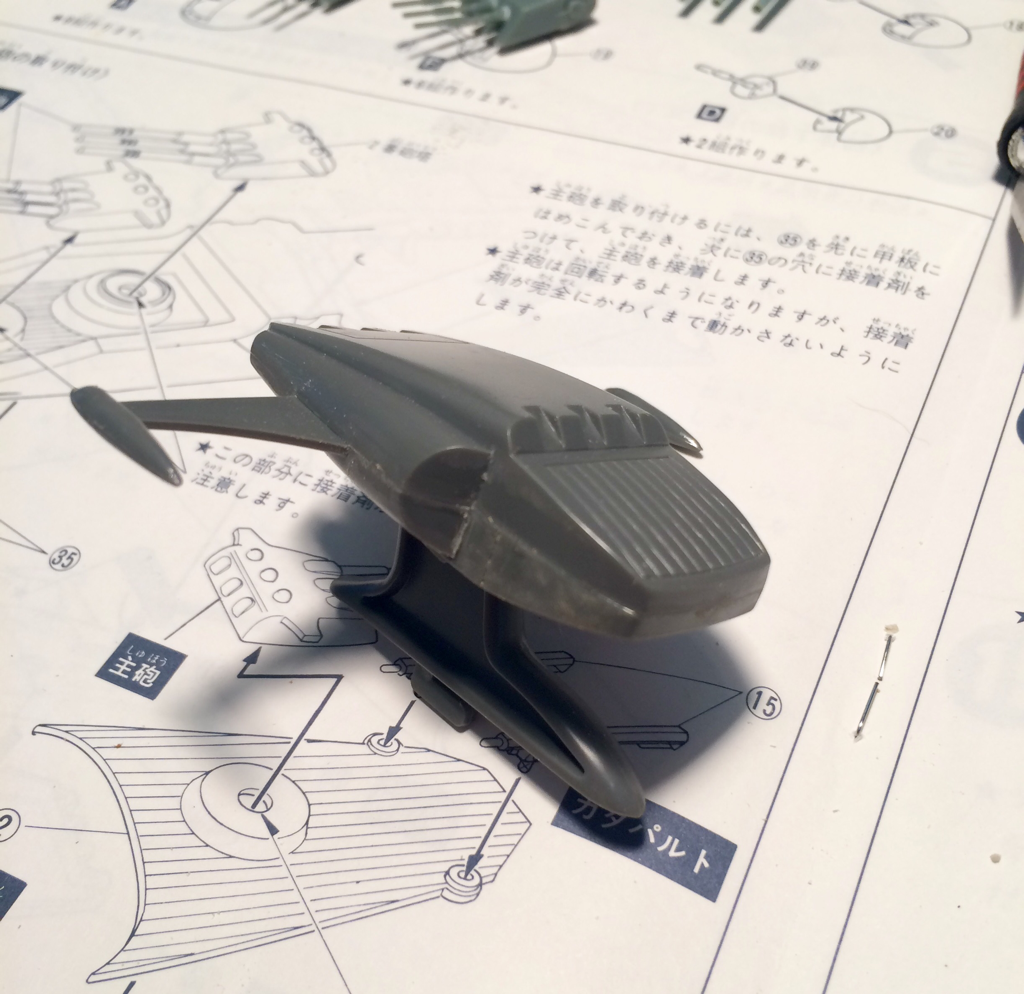
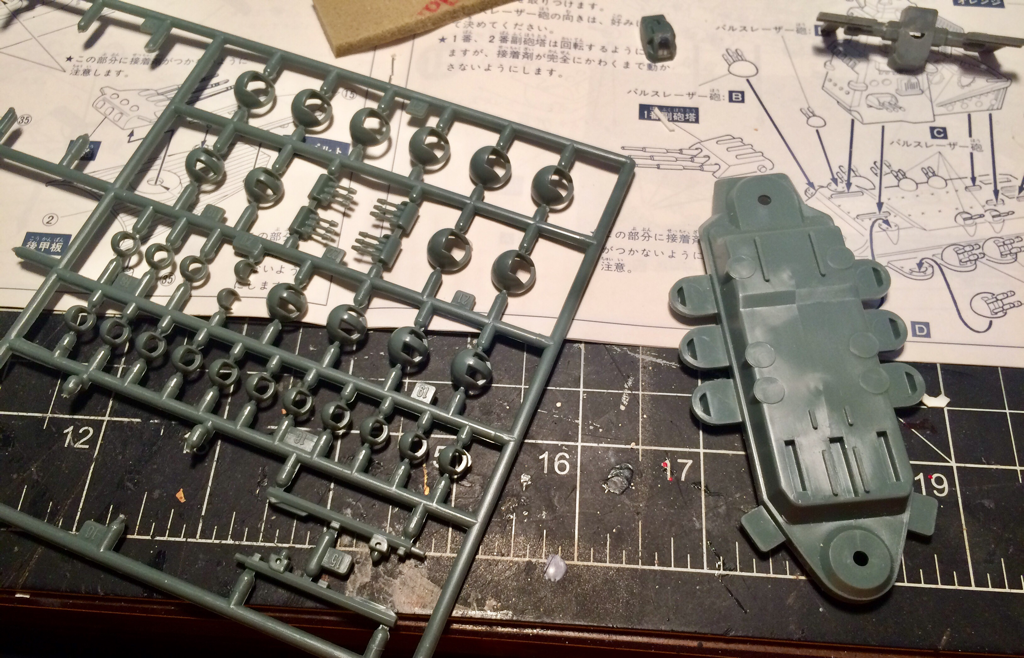
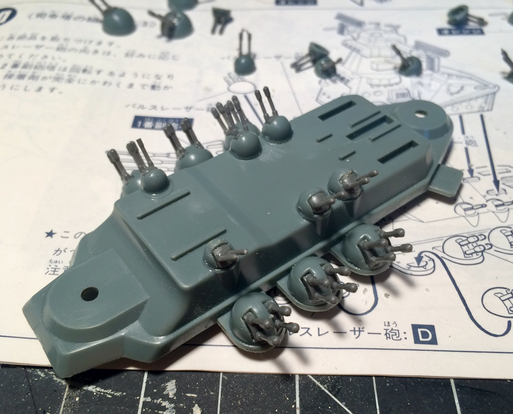
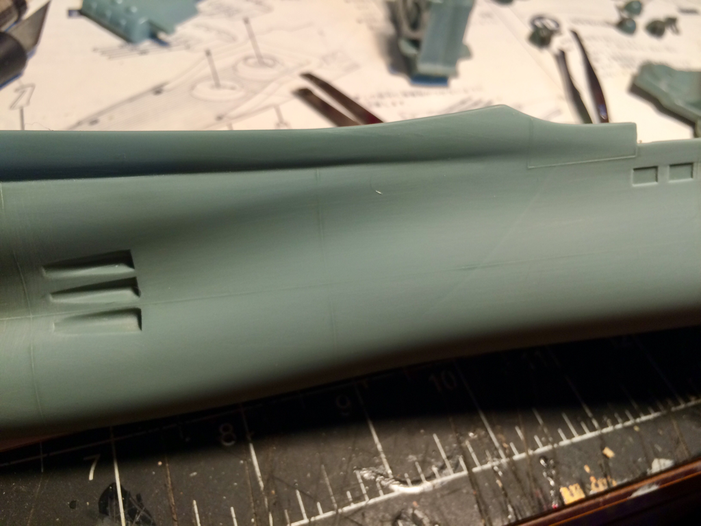
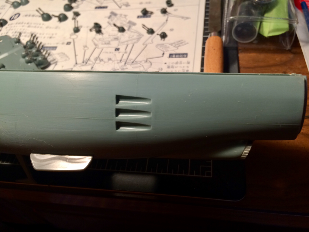
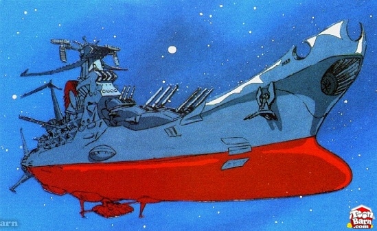
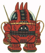
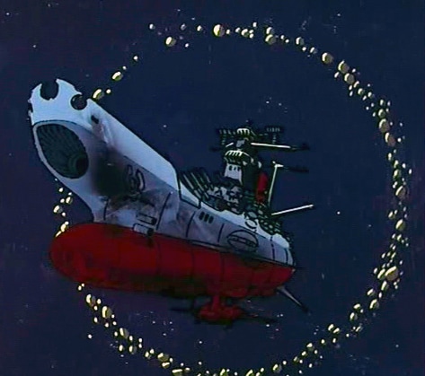
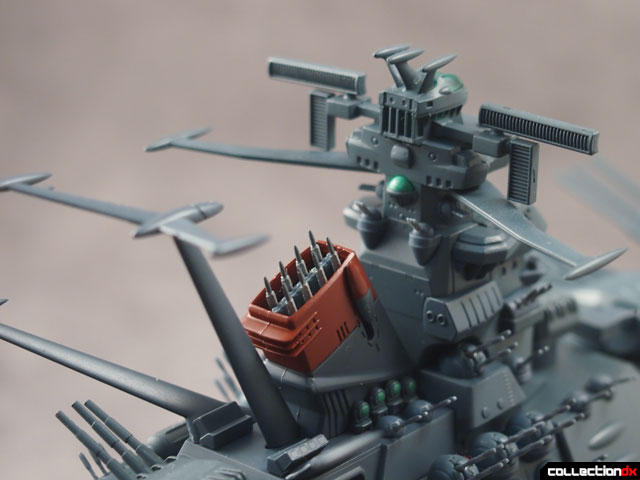
I tend to build my ship models in sections, building up subsections and prepping everything for painting. First the hull. I assembled the hull halves, added filler to the seam and then filled in the wing slots on the port and starboard sides. The Yamato has retractable wings used in atmospheric flight, sometimes, the show is not always consistence on the wing use. So as we’re displaying the Yamato in space the wings are off to the bits-box and the slots filled in. I then sanded all the raised panel lines off hull and smoothed all the filler. I’ll scribe the panel lines back in later. I cut the holes for lighting the windows in the side blisters, added the hull winglets, and blisters, and cut the holes for the secondary engine lights. While the hull was drying enough for me to start sanding and cutting on it, I assembled the main and secondary cannon turrets, if at all possible I’ll be lighting the side wings on the main gun turrets (these have green lights in the show). The main engine was then hollowed out for the lighting effects, I’ll be lining the inside of the engine with foil to better reflect the light for the LEDs.
The Conning tower was then assembled and the windows cut out and backed with clear plastic for the lights to shine through. I bit of sanding was needed to flatten the face of the tower for a good tight fit of the detail panels and the Captain’s tower. The Missile stack was then added, I’ll be detailing these a more later on. I also assembled the second bridge and test fitted it to the hull.
With the hull dry and sanded I cut out the landing/launch platform for the stern lower hanger. This will have the lower hatch extended with the inside of the hanger lit. However I slipped up a little, I over cut the opening and had to add a sliver of plastic back and add filler to correct my mistake. As the fix was drying I worked on the lowered launch platform, this was made from the removed piece of the hull with some styrene sheet added. I cut the retracting arms and attached them, then checked to make sure the fighter fit. I then cut the hanger box this will be the interior of the hanger, the inner walls will be covered with some artwork made on Photoshop. The hull need a little more filler in some places, so it’s STILL drying… Okay fine! I’ll work on the anti-aircraft batteries. There are a lot of these little buggers, but I got them all together and added them to the conning tower deck.
A final sanding of the hull and all the panel lines are gone, the seams are smoothed and the filler all cleaned up. I’m still debating on drilling out the torpedo tubes but I will be scribing in the blast vents for each tube.
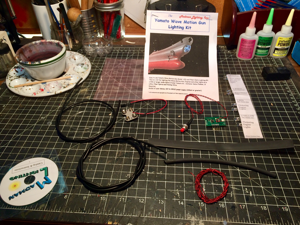
Okay that’s all for now… I’ll need to set up for the lighting next!!!
So until next time, Keep Building! "The 155 mm Long Tom was a 155 millimeter caliber field gun developed and used by the United States military. It was produced in M1 and M2 variants (later known as the M59). Developed to replace the Canon de 155mm GPF, the gun was deployed as a heavy field weapon during World War II and the Korean War, and also classed as secondary armament for seacoast defense. The gun could fire a 45.36 kg (100 lb) shell to a maximum range of 22 km (13.7 mi), with an estimated accuracy life of 1,500 rounds." - From Wikipida.com I built this as a retirement gift for a US Army Artillery Colonel. I decided to replicate a Long Tom from the Pacific Theater of operations during WWII. The Base is a wooden plaque purchased from a craft shop and covered in plumber's putty to model the ground. The ground was then painted and covered with static grass, sand and flocking for model trains. I modeled the wheel tracks in the mud using the wheels from the artillery piece and used the same putty to add the clumps of mud to the tires. The crew was bought separately and added to depict the team reloading during a barrage. I wish I had more experience on weathering when I built this, I would have done so much more with the mud, but all in all not a bad project.
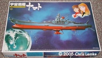
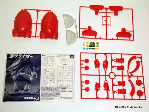
I found this kit on the HobbyLink Japan website. The kit is by Bandai a company well known for their quality and anime kits. Shipping was fast, price was good… on to the kit! What You Get. Two kits! No really, there is a small kit of IQ-9 a robot character from the series, but let’s start… The Yamato: The 1/500 scale kit comes in 4 trees, 2 hull halves, a deck section and pre-printed stand, for a total of 174 pieces in all, and this is a nice big kit over 20.86 inches long all told. The ship parts are molded entirely in battleship grey (how appropriate) and the 3 stand parts are molded in flat black. There are no defects or flash whatsoever, there are small mold lines but these are easily removed. All the major and some minor details are represented very nicely except for the raised panel lines in the hull (I would have preferred engraved panel lines). A couple of nice details that stand out are the massive amounts of “anti-aircraft” guns that flank the sides of the main conning tower (on the small scale kits many of these guns are often omitted), and the inclusion of three in-scale CosmoTiger II fighters, giving you the option the model them on the “catapults” or just display them alongside the kit for scale reference. There is only one small sheet of decals for the kit and these are for the stripe details on the barrels of the main turret guns. The instructions are very clear despite their being wholly in Japanese. The drawings and symbols are very clear for construction, however for painting the instructions are only useful to show you what to paint (by coloring the area to be painted in grey), those who cannot read Japanese will have to use the box art or other references for the correct paint scheme.
Assembly & Finish: Assembling this kit should be pretty straightforward: just like building a WW2 warship. The most difficult part will be the closing the hull halves cleanly and removing any seam mark, also the Yamato has retractable ‘wings’ on the hull for atmospheric flight, there will be left off so I’ll need to fill the slots for those as well. Most likely I will sand down the raised panel lines and inscribe them into the hull. The interior of the hull leaves plenty of open space if for lighting the kit, the base however has no way to hide the battery box so some extensive redesign on the base may be required. There may be painting instructions included in the directions, however I cannot read Japanese. That will not pose any difficulties as there are many web-based sources available, and the Series is available for purchase or rental on DVD.
Well there we go the next project all set to go onto the bench!
I’m off to watch some old Star Blazers episodes. Until next time, Keep Building!
Next up are the final finishing pieces, and the rigging of the ship. First I painted up the steer-board (this is where we get the word starboard) the steer-board was an offset rudder. Then I carefully painted the booms on the sails and added a light wash to the sails themselves. Finely the steer-board was then attached to the main deck. Now onto the rigging! The main sail and topsail was rigged to the aft of the ship, there should be a rigging bar located there but I used the railing to run the lines. The main boom and the main mast support lines were all rigged to the top deck where the crew would control the set of the sails. The foresail boom and sail was rigged to the rigging bar mounted at the base of the bowsprit. I then trimmed up all the extra lines and got ready to mount the anchors. The anchors are mounted to the bow. While the anchors dry into place I worked on the base and nameplate. A quick dry brush on the nameplate brought out the text.
So there it is, the Ancient Merchant-er is all done, a kit that is 2 years older than the builder! I hope you are enjoying my build logs!
We have a BIG project coming up, one with lighting and modifications! So until next time, Keep Building! |
AuthorHi there, I'm Chris and welcome to my workbench. I've been building models since i was 6 or 7 years old. I thought it would be fun to share some of my projects! Archives
May 2017
Categories |

 RSS Feed
